Terra 420 Manual
[ : Version 0.1] [ : 09/06/2025]
1. Introduction
With the Terra 420, AtlasAero presents a fully electric paraglider propulsion system that sets new standards in efficiency, safety, and user-friendliness. Developed for pilots seeking maximum independence and flexibility, the Terra 420 enables independent take-off on flat terrain – without any additional infrastructure.
Thanks to its universal compatibility, the motor can be combined with almost any standard seated or reclining harness, opening up a wide range of applications. The quiet, highly efficient drive unit not only ensures an unparalleled flying experience, but also particularly environmentally and neighbor-friendly operation.
Special attention has been paid to safety: modern sensor technology continuously monitors flight conditions, while innovative battery technology ensures exceptional durability and reliability thanks to replaceable cells, individual cell temperature monitoring, and the highest manufacturing standards.
The Terra 420 thus combines independence, efficiency, and safety—offering you a unique flying experience that focuses entirely on the essentials: the freedom of flight.
We would like to thank you for your purchase and your trust in the Terra 420. With this manual, we would like to help you use all functions safely and reliably so that you can enjoy many unforgettable flying moments.
2. Safety instructions
Important
Before you use the Terra 420 in flight, it is important to read the entire manual and familiarize yourself with the safety instructions.
In this chapter, you will find general safety-related rules and instructions.
2.1 Formatting
Safety-related instructions are clearly highlighted so that you can recognize them immediately.
For example, warnings and important safety instructions are presented as follows:
Warning
Indicates a potential hazard that could result in injury or damage if ignored.
Danger
Used when there is an immediate hazard that will certainly or very likely result in serious injury or death if ignored.
2.2 Requirements for pilots
The Terra 420 is approved as a foot-launched ultralight aircraft (UL) for paragliders and complies with the DGAC classification ULM Class 1.
As a pilot, you are fully responsible for informing yourself about the aviation regulations applicable in your country or flying area and for complying with them. In Germany, an ultralight motorized paraglider license is currently required for operation. Please note that different regulations may apply in other countries.
In addition to the legal requirements, sufficient practical experience in handling the paraglider is essential. We recommend regular ground handling and refresher courses to maintain your skills safely.
In addition, we strongly recommend that you take a briefing from AtlasAero or an authorized flight instructor before using the Terra 420 for the first time or after a long break from flying.
Briefing and support
If you have any questions or feel unsure in certain situations, you can contact us at any time. Our team will be happy to assist you with any questions you may have about the Terra 420.
In addition, we offer regular training courses and briefings – ideal for refreshing your knowledge or gaining new experience in the safe use of your power system.
2.3 Paraglider and harness
The correct choice and perfect condition of your paraglider and harness are essential for the safe operation of the Terra 420. Please note the following requirements:
- Only EN-approved harnesses and paragliders may be used with the motor.
- The combination of harness and paraglider must be approved by AtlasAero. You can find a current overview in the compatibility list.
Have compatibility checked
If your paraglider or harness is not yet listed in the compatibility list, you can contact us at any time. We will be happy to check this free of charge and let you know whether the combination can be approved for use with the Terra 420.
- The approved weight range of the paraglider must be strictly adhered to. Take into account the additional weight of the drive system.
- The paraglider and harness must always be in a technically safe condition for flying. The paraglider must have a valid check.
- It is mandatory to use a rescue parachute whose maximum permissible weight matches the total take-off weight. Ensure that the rescue device is regularly serviced and packed in accordance with the manufacturer's instructions.
2.4 Electrical voltage
The electrical system is equipped with numerous safety and protective devices, which are described in detail in the following chapters.
Most system components operate at a low voltage that is harmless to humans. Nevertheless, the utmost care must always be taken when handling electrical equipment.
Working on electrical equipment
Please note: Work on electrical equipment may only be carried out by persons trained and authorized by AtlasAero.
Orange cables
All live cables with higher voltages are marked in orange. These cables must be handled with particular care and checked regularly for damage.
If damage is found, the system or power supply must be deactivated immediately and the manufacturer consulted.
2.5 Magnetic fields
The Terra 420 battery emits increased magnetic fields due to the magnetic contact. These are harmless to healthy people and have no effect on normal operation.
Risk for people with pacemakers or medical devices
However, there is an increased risk for people with pacemakers or implanted medical devices. They must not use the aircraft and should maintain a minimum distance of two meters from the system.
2.6 Condition and maintenance
Regular maintenance and inspection is required for safe operation of the Terra 420 (see section Maintenance). This is the only way to ensure that the system is fully functional.
If damage to the device is detected or error messages appear, flight operations must not be carried out. In this case, it is essential to consult AtlasAero before using the system again.
2.7 Declaration of conformity
tbd
3. The most important components
3.1 Overview
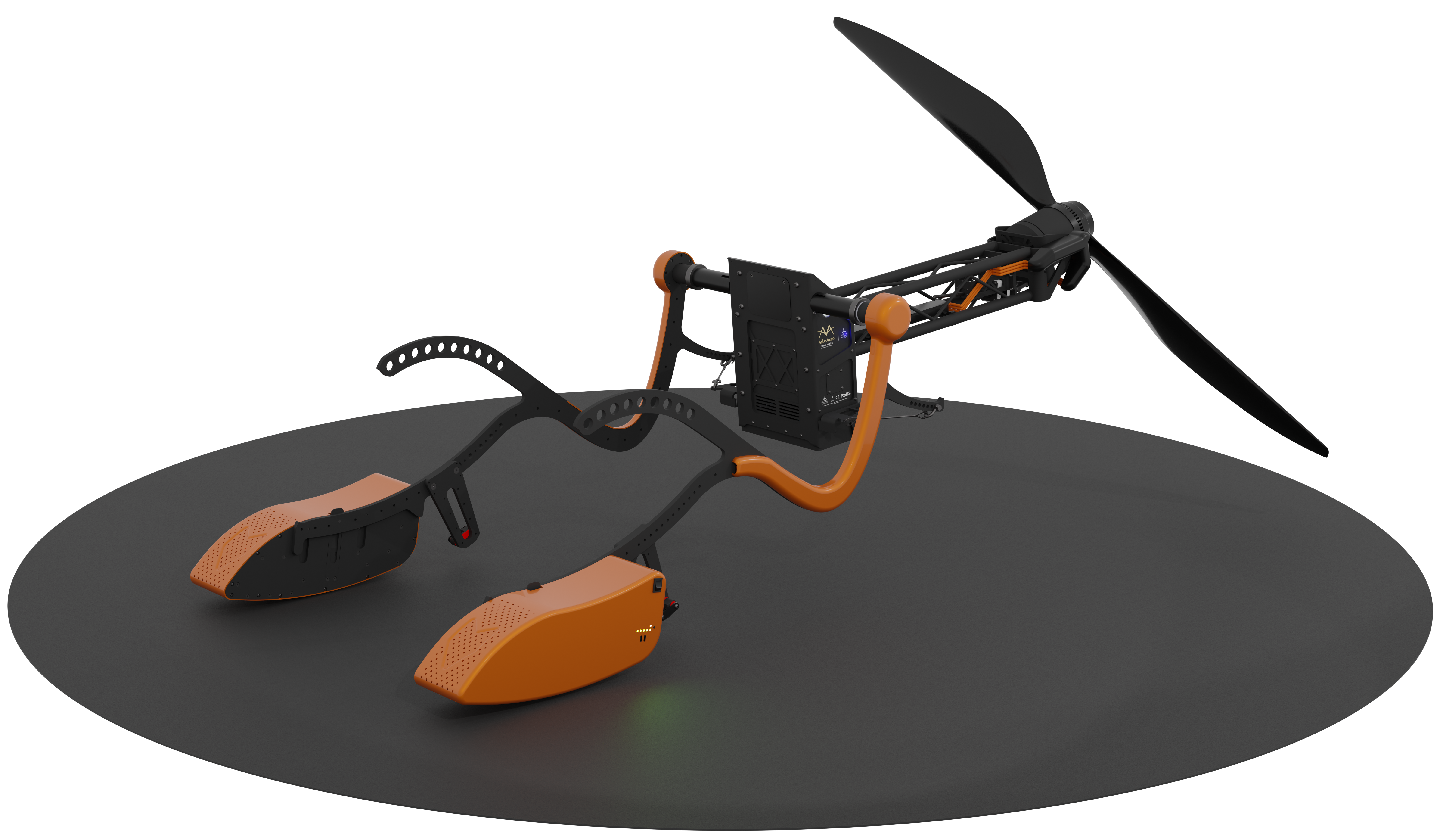
The following figure shows the most important components of the drive.


Figure 1. Main components of the drive with reference number
Main battery ➀-
Power supply for the drive
Damping ➁-
Dampens vibrations between the push rod and the harness (see section Damping).
Thrust rod ➂-
Connection between harness and drive
Back section ➃-
Connection between drive and thrust rod ➂. Contains the electronic components (e.g., flight controller)
User panel ➄-
Main switch and LED indicators of the flight controller - (see section User panel).
Type plate ➅-
Sticker with type designation, serial number, and QR code for pairing with the Cockpit app
Thrust transducer ➆-
Transfers the thrust to the thrust rods with the following subcomponents: Thrust transducer trim ⓐ, connecting cable ⓑ, and attachment point ⓒ
Crossbar ➇-
Connection between the motor mount and the rear section. Runs the phase cables to the motor
- Spindle motor ➈
-
Drives the swivel mechanism of the motor mount.
- Swivel motor mount ⑪
-
Swivel mount for the motor to adjust the thrust angle, up to complete retraction
Main motor ⑫-
Sets the propeller in rotation to generate thrust
Propeller ⑬-
Generates thrust through rotation
Propeller quick release ⑭-
Screwless attachment of the propeller. 1
3.2 Back section
tbd
3.2.1 User panel
The user panel ➄ is located on the left side of the back section ➃.
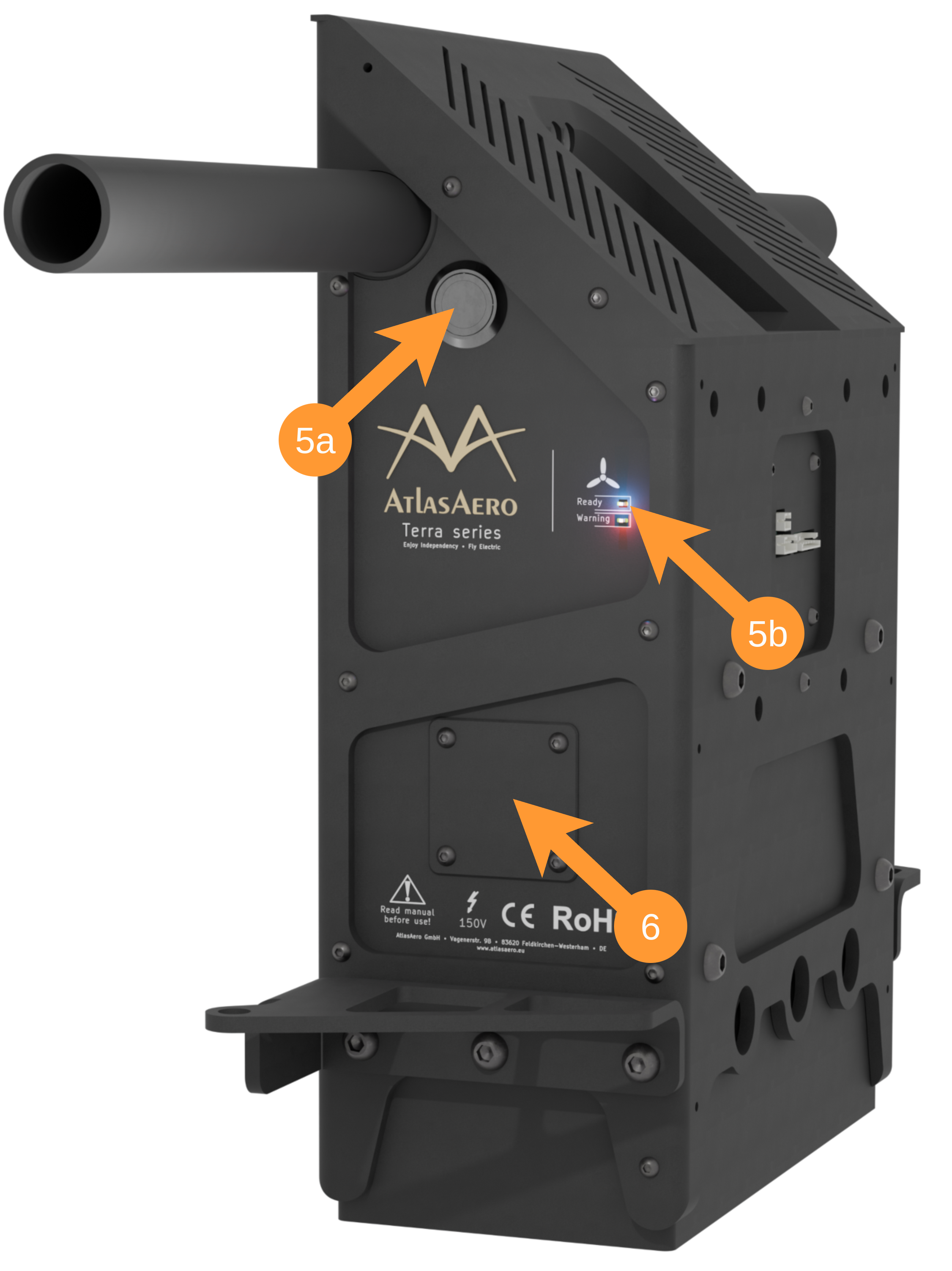
Main switch ➄ⓐ
The flight controller can be switched on and off using the button:
- To switch on, press the button briefly until it lights up white.
- To turn it off, press and hold the button for at least 3 seconds.
As a secondary function, the main switch can also be used to initiate battery pairing.
Blue "Ready" LED ➄ⓑ
Lights up blue continuously as soon as the system is fully booted up and ready for operation.
Figure 2. Detailed view of the user panel
Red "Error" LED ➄ⓑ
Lights up red when an error has occurred. Details on the type and cause of the error can be found in the cockpit app.
Please check the information displayed there before continuing flight operations.
Type label ➅
There is a label in the lower section that contains important identification data for the device:
Type designation and serial number: This information is used to uniquely identify your drive, for example for service or warranty inquiries.
QR code: The printed QR code enables pairing with the Cockpit app. Scan the code within the app to establish the connection and use all the app's functions.
3.2.2 Central Electronic System - CES
tbd
3.2.3 Motor controller - Neomium type CS-40
tbd
3.2.4 Propeller Positioning System - PPS
tbd
3.2.5 Thrust sensor
tbd
3.3 Handheld controller
The control system was developed with the aim of working with common Bluetooth handheld controllers in order to be as flexible and reliable as possible.
Currently, the drive is delivered with the C1 model as standard. This model was deliberately chosen because its small number of buttons makes it particularly easy and intuitive to use – even when wearing gloves.
In the future, we plan to extend compatibility to other control devices to offer you even more flexibility for different flight conditions and personal preferences.
3.3.1 Button assignment
The following figure shows the button assignment for the C1 hand control:
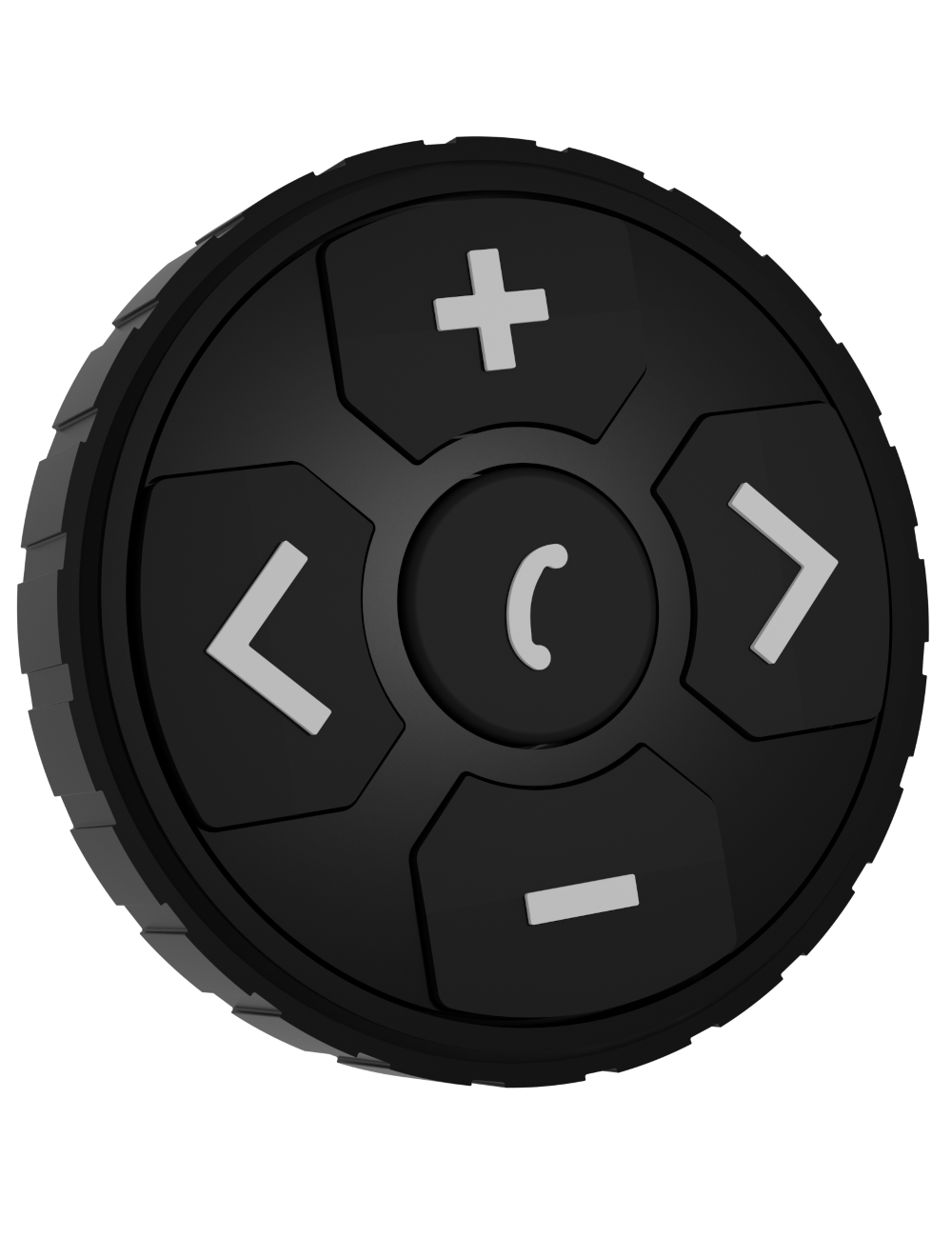
Left button : Activates and deactivates the drive.
Middle button : Turns the propeller thrust on or off.
Upper button : Increase thrust or propeller speed.
Lower button : Decrease thrust or propeller speed.
Right button : Fold or unfold the propeller.
Figure 3. Hand control C1
Depending on the flight status and phase, certain buttons on the hand control are automatically deactivated to ensure safe operation. For example, individual functions may be locked during takeoff or climb to prevent unintended inputs.
A detailed overview of the button functions and their availability in the individual flight phases can be found in later chapters.
3.3.2 Switching on and off
Switching on:
Press and hold the middle button until the LED on this button lights up. After switching on, the hand controller automatically connects to the flight controller.
Once this connection is established, the icon in the upper right corner of the Cockpit app will turn green.
Switching off:
Press and hold the right and left buttons simultaneously until the LED on the middle button lights up.
Then release briefly and press both buttons again until the light on the middle button goes out. The hand controller is now completely turned off.
3.3.3 Charging
The hand controller can be charged via the USB Type-C port. Use a standard charging cable for this.
The current charge status of the hand control is displayed in the cockpit app – right next to the keyboard icon .
Check charge status
Check before each flight that the hand control is sufficiently charged.
3.4 Automatic launch
tbd
3.5 Sensors in the paraglider
tbd
3.6 Push rods
tbd
3.7 Damping
The damping ➁ creates an additional connection between the harness and the push rod, in addition to the carabiner. This dampens movements between the harness and the push rod and prevents the drive unit from "swinging through," especially during takeoff.
Defective propellers
An incorrectly attached damper significantly increases the risk of the propeller contacting the ground during takeoff.
Therefore, always check both dampers before each takeoff.
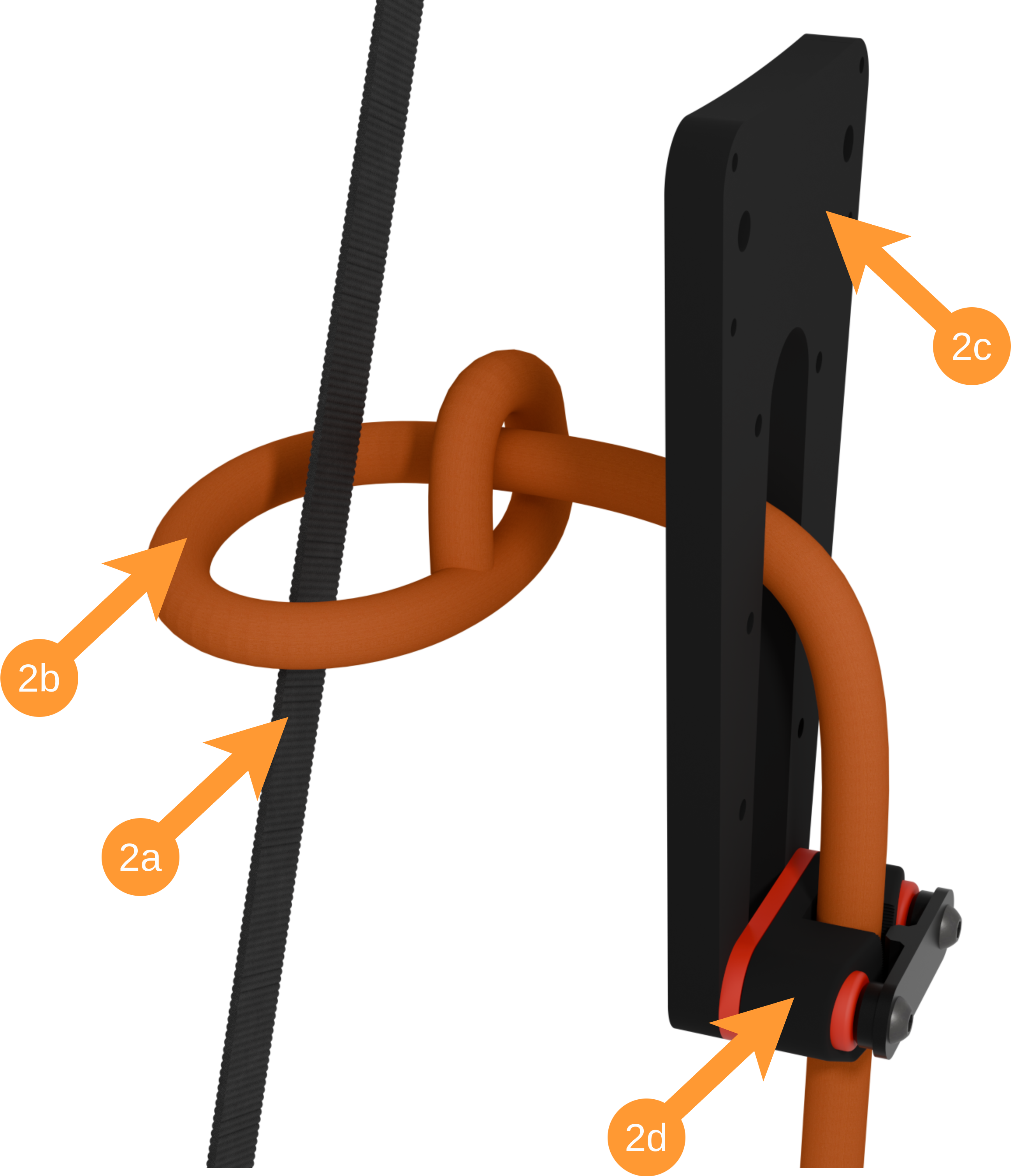
To attach the damper ➁, place the connecting rope ⓐ around the main suspension ⓑ of your harness and then thread it through the rope loop and the slot of the damper element ➂ of the push rod ➂.
Finally, thread the rope ⓐ through the bulkhead clamp ⓓ and tighten it.
Figure 4. Connecting the shock absorber to the main suspension
Identifying the main suspension
The main suspension is the load-bearing connection between the harness carabiner and the seat board or leg loops.
To identify it, sit in your harness and look for a wide strap under load that runs from your carabiner towards the seat pad.
3.8 Main motor swivel mechanism
tbd
3.9 Propeller quick release
tbd
3.10 Battery system
3.10.1 Left and right main batteries
tbd
3.10.2 Auxiliary battery in the back section
tbd
3.11 Cockpit app - smartphone
tbd
3.12 Accessories
3.12.1 Hanging rack
tbd
3.12.2 Transport bag
tbd
3.12.3 Back carrying set
tbd
4. One-time preparation
4.1 Attaching the harness
tbd
4.2 Adjusting the harness
tbd
4.3 Adjusting the trim
tbd
4.4 Cockpit app
tbd
4.5 Paraglider sensors
tbd
4.6 Coupling batteries
tbd
5. Before the flight
5.1 Transport
tbd
5.2 Set up suspension frame
tbd
5.3 Prepare drive
5.3.1 Unfold drive and attach thrust sensor
tbd
5.3.2 Mount propeller
tbd
5.3.3 Attach and connect batteries
tbd
5.3.4 Start up system
tbd
5.3.5 Activate sensors
tbd
5.3.6 Check system
tbd
6. Before takeoff
6.1 Put on harness
tbd
6.2 Disconnect from hanging frame
tbd
6.3 Attach paraglider
tbd
7. During takeoff
tbd
8. During flight
8.1 Flight instruments and displays
tbd
8.2 Controlling and regulating thrust
tbd
8.3 Deactivating and folding up the drive
tbd
8.4 Unstable flight conditions
tbd
9. Landing
9.1 Correct propeller position
tbd
10. Maintenance and care
10.1 Software updates
tbd
10.2 Inspections
tbd
11. Contact
tbd
-
AtlasAero's own invention. Protected by utility model
DE20 2022 002 499.1↩